Tuesday, 13 December 2011

Basic Cameras

 Camera Tutorial

There a two types of camera available in 3DS Max.

Target Camera:

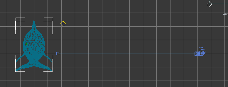
This is used for looking at a direct point in a scene. For an example I can aim a Target Camera at the dolphin in the scene and set the target as the dolphin, this way I can set key frames in the animation where the camera is moved but the camera will always point at the dolphin.


Free Camera:
A Free Camera is used in a scene when the camera would just be having a view of what is in the scene and it wont follow any object. For an example placing a Free camera in the scene facing the dolphin will have a view of the dolphin but when the dolphin is moved it will be out of view and the camera would need to be manually moved to be able to see it again.

Monday, 12 December 2011

Sky Dome

 Creating the Sky Dome

This was the texture I chose for the Sky Dome, I picked this because it gives a great effect of space and as the Death Star is in space it gives a great feel of how vast and empty it is.

Accessed 12/12/11 - http://media.bigoo.ws/content/background/space/space_154.gif

I used the same method as in the Sky Dome tutorial but as the Death Star is floating in space there was no ground as such so I needed an entire Geosphere instead of a Hemisphere so that space could be seen from every direction. I still used the NORMAL modifier to put the texture on the inside of the Geosphere and Flipped it.


I used a UVW map to change the way the texture was projected onto the Geosphere and I ended up using the 'Box' map as it projected the texture in the correct way to make it look best.

This gave a perfect looking scene for my attach on the Death Star.

Lighting Tutorial

Lighting Tutorial

Lighting is used to change the way object are lit in a scene. When applying a new light in the scene it will automatically turn off any default lighting that 3DS Max has put in.

Spot Light - Casts a light outwards in a cone shape.

Direct Light -  Similar to a Spot Light but casts light out in one direction in a cylinder shape of a rectangle shape rather than a cone shape.

Omni Light - Casts the same amount of light in every direction.


For this tutorial I used an Omni Light, this casts light onto one side of the dolphin but disables any other light sources around it.


As you can see from looking at the opposite side of the dolphin there is no light sources behind it so therefor it is dark.

Sky Dome Tutorial


Sky Dome Tutorial

As I needed a sky dome to put around the Death star to create the effect of space so I did the sky dome tutorial to learn how to do this correctly.
I started using a Geosphere which would go round the outside of all the models in the scene.


Changing the Geosphere to a hemisphere cuts the shape in half so that it only covers from the ground and not all the way underneath. The hemisphere needs to be set just lower than the ground so that the edges are not seen.


With my hemisphere set I needed to apply a texture to it. The problem is that if I apply a texture directly to it, the texture will be on the outside of the hemisphere. To solve this problem I needed to add a NORMAL modifier to it and enable the FLIP NORMAL option, this then puts the texture on the inside of the hemisphere instead of the outside.

To make the hemisphere more realistic it is a good idea to lower the top of the hemisphere. For this I will use an XFORM modifier, this allows it to be animated easier and it can be used to modify any layer in the stack. On the gizmo layer of the modifier the hemisphere is modified to look like this.

Death Star Texturing

Death Star Texture

This was the texture I used for the Death Star. It is a seamless tile which was perfect to use as it didn't leave an obvious line where the texture met up with itself.
This texture also defined the trenches in the Death Star which was useful as I could then Boolean out the trenches where they were on the texture.


For this model I wanted a quick way to cut into the texture to create an uneven effect as the Death Star isn't just a smooth sphere I wanted it to show where edges were cut out.

To achieve this I used a bump map, The bump map takes a texture and then allows you to either pull in or extrude the darker areas of the texture.


Loading the texture and then lowering the amount of the bump map down created the perfect uneven texture I was looking for. The problem I found with this was it didn't actually display the texture as well as the bump map so to solve this problem I also added the texture under the Diffuse Colour as well so that the texture was displayed as well as the bump map.

I also noticed that the bump map would only be displayed with the frame was rendered so when I was adjusting the height I had to keep rendering the image to check it was at the right height. As the model was a sphere I didn't need to bother with a UVW unwrap again as I could project the texture directly onto the model.


As the bump map only cuts into the model small amounts I had to manually cut out the bigger trenches. To to this I created large tubes that I could adjust to Boolean out small cuts all the way around the model. I also used a Mesh Smooth modifier to make the tubes have a much rounder shape.

I simply went round the model adjusting the size of the tube and cutting out each trench. It was essential that I got the Boolean size just right as the cuts were all at an angle, If they were too big It made the model look strange from a distance so this was a very long and tedious task.


With the laser of the Death Star I chose not to use a texture as it was a simple object that worked perfectly well with just a colour applied to it.


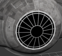
When creating the Death Star I had forgotten to create the main whole that the X Wing was going to shoot down to destroy it so I added this to the main trench by using a cylinder and Boolean it out.


Overall the Death Star was a simple object to create but as it was also going to be used as my landscape I had to make sure it had enough detail for this.

This is what the Death Star looked like without the bump map.


But when rendered you can clearly see how the bump map has affected the texture and it makes it look a lot more realistic.

Sunday, 11 December 2011

Tie Fighter Texturing

 Texturing the Tie Fighter


This was the texture I chose to use for the main body of the Tie Fighter.


Accessed 10/12/11 - http://www.kaneva.com/mykaneva/PictureDetail.aspx?assetId=6231784

As I wanted the texture to just wrap around the body I didn't need to use a UVW map as I didn't need to texture individual parts. So I simply used the material editor to project the texture directly onto the body.


For the wings of the Tie fighter I needed to use Photoshop to manually draw the texture on. So I used the same process as I did for the X Wing and exported a UVW unwrap that I could use in Photoshop.


To create the texture for the wings I used a dark black for the main colour of the wings and then layed grey lines over the top to create a similar effect that the Tie Fighter has.

I also added grey rectangles over the edges of the wings to replicate the sides.


When I was happy with the texture I used the materials editor to put the UVW unwrap back onto the model and it looked like this.


I used exactly the same procedure with the window that was in the main body of the Tie Fighter.


I used a large white circle for the outer ring and then put another slightly smaller circle inside that with a black colour to create the window. Then I used white lines on top of that to define the edges of the frame.

When put back onto the model it looked like this. Doing it this way clearly defined the window so it didn't look merged with the main material.


This gave me a final model that I was happy with and was ready to use it in my main animation.


Texturing my X-Wing Ship

 Body and Wing Textures

For my X-wing I needed to texture individual parts of the ship so I couldn't directly use the materials editor to just project a texture on. I used the UVW unwrap modifier to achieve this, the UVW unwrap modifier essentially takes the selected faces of an object and displays them in a format that can be easily edited. To make things easier for myself I used multiple UVW maps, this way I could texture over the entire model bit by bit and the maps are much simpler to understand.

Below is a UVW map for the main body and the wings of the X-wing. There are various options for displaying the map under the 'Mapping' tab such as 'Normal' 'Flatten' and 'Unfold'. This map is flattened to show every edge if the body and wings.


The map then has to be rendered in order to be exported. This is what it will look like when saved as a JPEG. With this map of my ship I can start texturing it.


These are the two main textures I selected to use for these parts of the ship.

The first one is a light grey colour with small marks in it making it look uneven and worn like a ship would be.

Accessed 06/12/11 - http://hhh316.deviantart.com/art/Seamless-metal-texture-smooth-164165216

I picked this texture to use on the wings as they are made up of various colours and shapes giving the impression of electronics and parts that are inside the wings of the ship.

Accessed 10/12/11 -http://www.filterforge.com/filters/2153.html

Using Photoshop I imported the the UVW map as well as my textures. As you can see in the below image I simply cut shapes out of my textures and placed them over the shapes where I wanted that texture to go. One large problem I ran into was the fact that once the map was flattened I had no idea what came from where. For example the tops and bottoms of each wing looked identical to each other so I had no idea which was which. To solve this problem I started by placing texture onto just one wing and then loading it back in 3DS Max to check it. To load the map back in 3DS Max I used the Materials Editor to project the image directly back onto where it came from. I saved the map as a .PSD file so it could remain editable within Photoshop, A big advantage to putting textures on this way meant that I could keep adding bit by bit to the map and saving, then it would automatically be updated within 3DS Max as I was directly editing the source file.

Some of the smaller parts of the map such as the nose, cockpit window and rear of the ship needed different textures to the body and the wings but I felt that it was unnecessary to use created textures as they were such small parts, instead I just used colours to complete these parts.


When I was happy with what my map looked like I just saved it again and it automatically updated within 3DS Max. This is what the body and the wings looked like when textured:


Engine Textures

For the main engines I used the same technique to export the UVW Map from 3DS Max but as the engines were rounded objects I used 'Normal' mapping instead of 'Flatten' mapping because this would have created many edges to texture due to the rounded shape. Using the 'Normal' mapping gave me a nice simple view of the tops and bottoms of each engine.


This is the texture I selected for the engines. I picked it because it has a similar effect to the texture of the wings but its different enough to clearly separate them from each other.

 Accessed 10/12/11 - http://www.kaneva.com/mykaneva/PictureDetail.aspx?assetId=6231784

As I just wanted the image wrapped around the engine it was just a matter of placing cut outs on top of each engine. Normally in situations like this I would just load the texture straight into the materials editor and project it on but in this case I wanted the detail to be small and repetitive so I chose to do it this way. If I had used the materials editor to directly put the image on it would have created a large stretched image around the engine.


This is what the engines looked like once I had applied the texture. It is possible to see the lines where the texture ends and connects back to the start of the texture but I felt it blends with the square jagged shapes enough not to worry about.


Gun Textures

As the guns were also rounded object I exported them in exactly the same was as the engines.


 This is the texture I selected for use on the guns. I was only keen to use the darker areas of the texture as they has the effect of buttons and a dark metal colour that you might find on a gun. So before applying the texture I used Photoshop to cut these areas.

 
Accessed 10/12/11 - http://www2.zbrushcentral.com/zbc_uploads/user_image-1006151658pji.jpg

I then simply put these images on top of the guns on the UVW Map. Again I did it this way rather than directly through the Materials Editor so I could have more detail and keep things small.


and had kept with similar colours to the rest of the ship but with enough of a colour change to be able to spot the differences.


Robot Texture

For this UVW Map I exported the map for the 'Vertex' level of the modifier, This was because I simply needed a top down view of the sphere that I could texture from the inside out and it would automatically stretch the map back over it.


This didn't use any textures from the Internet I just layered various grey and blue filled circle shapes on top of each other and then erased sections of the blue to give the uneven effect that R2D2 has in the film.


When applying the map back to the shape the Materials Editor stretched the  map over the sop of the shape just like a hat.


This gave me my final fully textures X-Wing fighter.